

Skip to content
TigerVision
Contact us
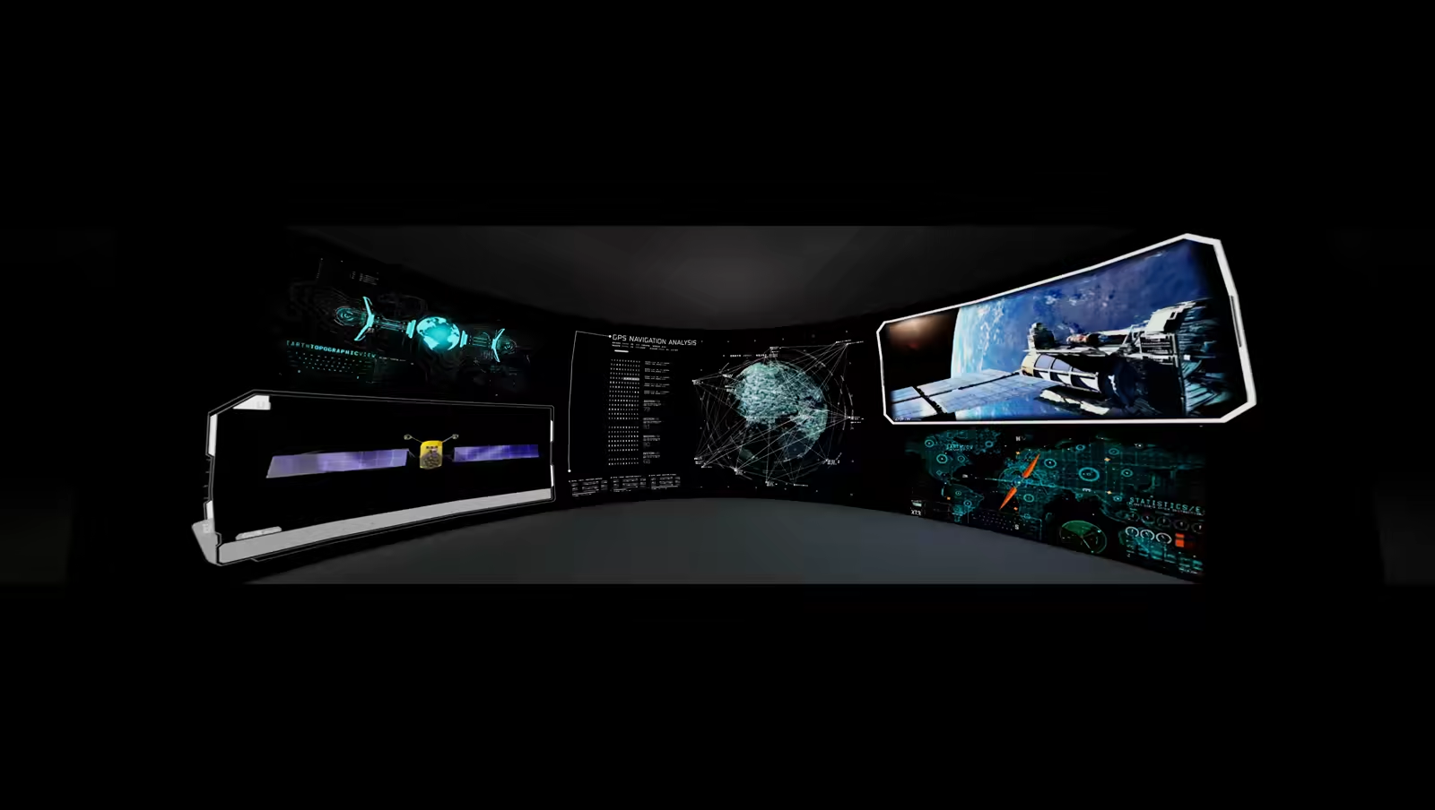
A Surround Reality volume, seen from the design eyepoint.
TigerVision

Scroll to continue

Surround Reality™

Put yourself in the picture.

Surround Reality™

Every system we build is patented direct-view LED, mounted spherically — emissive pixels on a compound curved surface, not projection, not optics and not a headset.
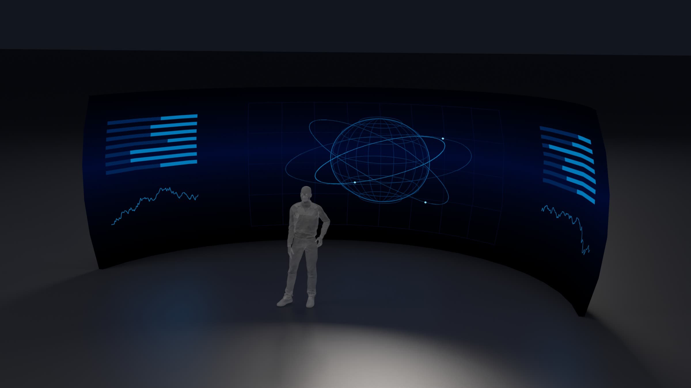
Studio render of the R14: a wide curved LED surface seen from inside the curve, lit with abstract orbital graphics, a standing human figure at its centre for scale. The display plane is 28 ft across.
The R14, the most-fielded family in the line. Rendered from the product geometry. Screen content is illustrative.

An unwarped, true spherical rendering — for one user or for a team.

Angular resolution is preserved at the design eyepoint. The display requires no pre-warping and no edge blending, and contains no seams and no facets — uniform resolution everywhere the eye lands.
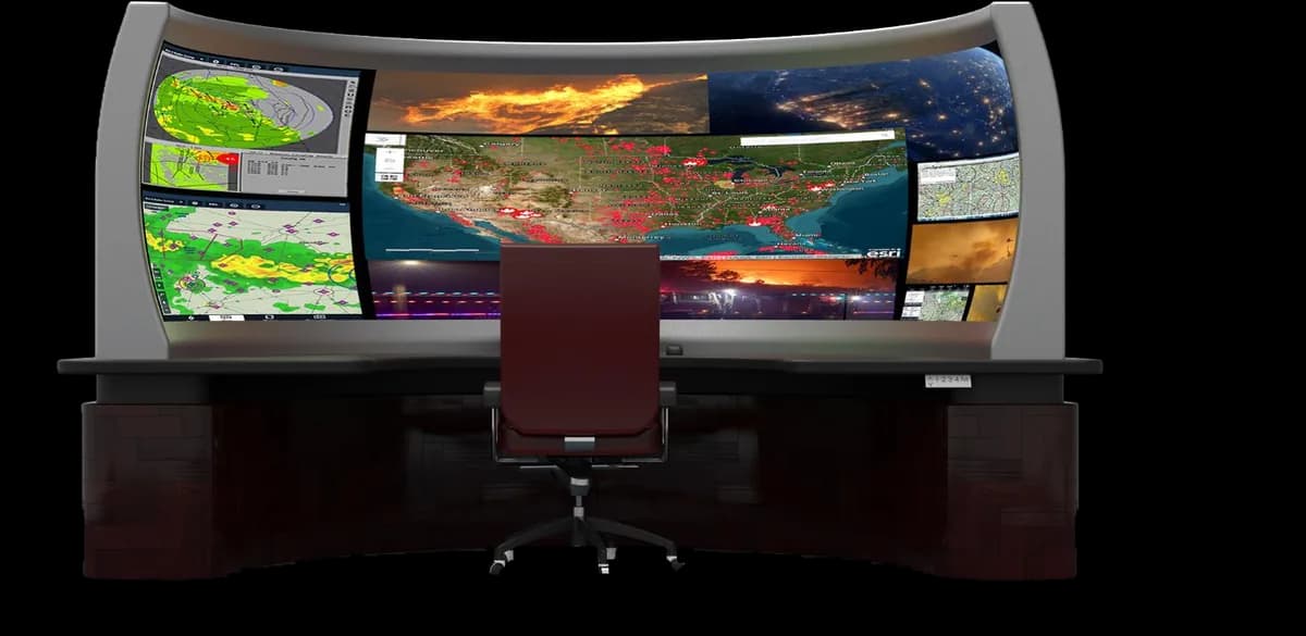
Concept render of an R5 at a single-operator desk: a curved LED surface spanning the width of the console and wrapping toward the viewer at both ends, carrying mapping, weather and live-feed panels, with one chair at the design eyepoint.

For one user — the R5, at a single-operator desk.
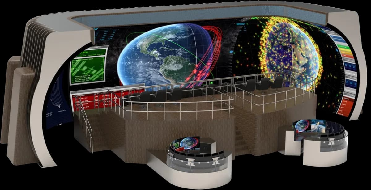
Concept render of a transitional fixture on an operations floor: a long curved LED run with a curved section returning at either end, carrying around a railed, tiered deck seating roughly a dozen people, all of them inside the same surface, with two consoles on the floor below.

For a team — a transitional fixture, on an operations floor.

Concept renders, not photographs. The content shown on the LED faces is illustrative — it is not a reading, a data product, or an integration with any named system.

Mission requirements determine the geometric boundaries.

How far the surface carries around the viewer and how far it carries above and below the eyeline are two separate numbers, specified independently. Horizontal coverage runs from 112.5° to a full 360°. Vertical extent runs from a band at eye level to a closed top. Uplook, look-down, full immersion and data visualization each ask for a different answer, and the system is configured to the one the mission actually needs.

Horizontal coverage, in planLooking down on the design eyepoint at the centre of the sphere. Three arcs show how far the surface carries around the viewer: 112.5 degrees, typical for command and control; 180 degrees, typical for a simulator; and 330 degrees, fully immersive. The copy notes coverage runs to a full 360. Each arc is part of the same circle, drawn dashed where none is built.330°FULLYIMMERSIVE180°TYPICALSIMULATOR112.5°TYPICALC2eyepoint

Plan — how far the surface carries around the viewer.

Vertical extent, in sectionA vertical slice through the same sphere, the design eyepoint at its centre and the eye line running horizontally through it. The built surface is drawn symmetrically about that line, carrying a variable uplook above it and a variable look-down below. Arrows continue past both ends in opposite directions to show that neither boundary is fixed: the upper one carries over the top and down the far side, as far as a closed top, and the lower one continues a shorter way below. The two are specified separately from the horizontal coverage.eye lineto a closed topuplookVARIABLElook-downVARIABLE

Section — how far it carries above and below the eyeline.

Both drawn about the design eyepoint, at the centre of the sphere. Solid where a surface is built, dashed for the rest of the sphere it belongs to. The two angles are specified independently — neither is a property of the product, and the drawings are schematic rather than a configuration on offer.

When the facility is the constraint.

Limited ceiling height. Structural columns in inconvenient places. A floor plate that was never going to hold a sphere. The mission still comes first — but where the building will not accommodate the purest expression of Surround Reality, transitional fixtures carry the same environment into the space you already occupy.

They produce immersion across a range of geometries — flat or cylindrical runs joined at the corners by compound-curved sections — so the display follows walls that already exist. Stringent program requirements can be met inside existing buildings, without demanding a new or heavily modified structure.
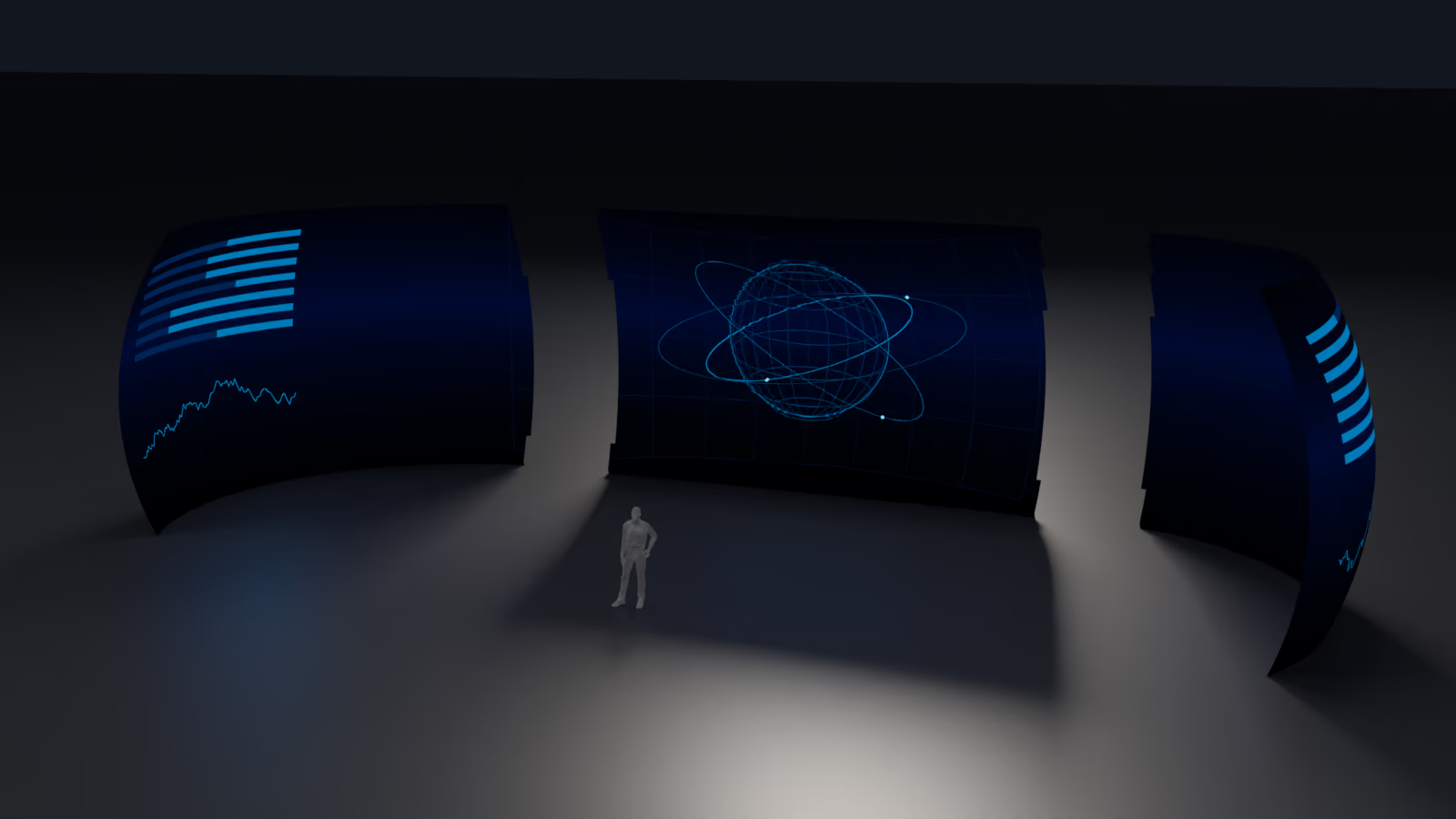
A transitional fixture in a dark studio, separated into the three sections it is built from: a compound-curved return at the left, a flat or cylindrical run across the middle, and a second compound-curved return at the right, with a standing figure at the centre for scale.
An R20 extended surround, drawn apart to show how the geometry is specified: a flat or cylindrical run with a compound-curved section returning at either end. The delivered surface is continuous — no bezels, no blend zones and no facets at the joins — so these are sections, not seams you would see. Rendered from the product geometry; screen content is illustrative.

Fielded systems and reference installations

  1. 01 · R14

    NASA Johnson Space Center, Houston, Texas

    2026Installed and in service.

  2. 02 · R6

    The Forge, Patrick Space Force Base, Florida

    2025Nine months of continuous testing — the longest evaluation run on any TigerVision volume.

  3. 03 · R6

    National SpacePower Center, at Sedaro, Alexandria, Virginia

    2026That same R6, removed from Patrick and recommissioned here.